
IMT Precision on the Print Review: Four Design Choices That Decide What a Large Part Costs
November 4, 2026

The Print Review, No. 1. For design engineers who want to know what a drawing really asks of a shop.
Ask a buyer why a machined part came back expensive and the answer usually points at the shop: the hourly rate, the material surcharge, the lead time. Ask a programmer and you will hear something different. Most of the cost was settled weeks earlier, at a CAD workstation, by someone who never expected to watch the part go onto a machine.
That gap widens as parts get bigger. On a ten-inch bracket, an extra setup is an annoyance that adds minutes. On a large structural component, it can mean lifting the workpiece off the table, turning it with an overhead crane, re-indicating it and proving the datums again before a single chip is cut. The same line on a print carries a very different price once the part is measured in feet.
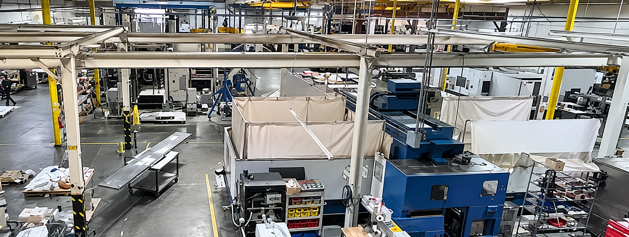
IMT Precision machines and fabricates large-envelope components at its Hayward, California facility, and its quoting team rarely sees the same part twice. Most of the work is one-offs, so every print decision is priced once, with no later run to absorb it. This first installment of The Print Review looks at the four print decisions that move that price the most.
Cost is decided at the print, not the quote
A quote is a reading of a drawing. Every callout tells the estimator how many setups the part needs, which tools can reach which features, how long inspection will run and how much risk the shop carries if a dimension drifts. Those inputs sit next to the others that make up an IMT quote: material, outside processing (OSP) and lead time when a job has to be expedited. The drawing drives the first group and often the second. By the time a buyer sees a number, those choices are already locked in.
That is why the cheapest conversation about cost happens before the RFQ goes out. An engineer who understands what a shop reads into a print can take real money out of a part without changing what it does.
1. Tolerances applied where they are not needed
The most common cost driver is also the quietest. Many drawings carry a tight default tolerance in the title block, and that default lands on every dimension without its own callout. A mounting face that genuinely needs to be held closely ends up sharing a spec with a clearance pocket that could vary far more and never matter.
Each tight dimension has a cost the drawing does not show. It can slow feed rates, add finishing passes, shorten tool life and send the part into longer inspection on the CMM. On a large part the inspection side grows quickly, because a big workpiece takes longer to measure and is more sensitive to temperature while it is being measured.
The fix is not looser engineering. It is deliberate engineering: hold the features that drive fit and function, and let everything else fall back to a sensible general tolerance.
2. Datum schemes that force extra setups
A datum scheme tells the shop where to measure from. When the datums sit on faces that cannot all be reached from one orientation, the part has to be repositioned to machine and inspect against them. Every repositioning is another setup.
On small parts, extra setups mostly cost time. On large ones, they add handling risk as well. Moving a heavy workpiece means crane time, new fixturing and careful realignment, and each move opens the door to stack-up error between features cut in different orientations.
Engineers can often avoid this by choosing datums the shop can establish from a single setup, or by grouping critical features so they are cut together. A short conversation about how the part will sit on the machine can save several setups later.
3. Internal corners and tool access
CAD software will happily draw a sharp internal corner. A spinning cutter cannot make one. Every internal corner in a machined pocket carries a radius equal to the tool that cut it, and when a print calls for a small radius deep in a pocket, the shop has to reach for a long, slender tool that cuts slowly and deflects easily.
Deep pockets with tight corners are a familiar trap on large components, where features tend to run deeper and walls stand taller. Specifying the largest corner radius the design can accept, and keeping pocket depth in proportion to that radius, lets the shop use stiffer tooling and faster, steadier cuts.
Where a mating part truly needs a sharp corner, there are usually alternatives, such as a relief cut, that achieve the fit without forcing an expensive tool into a deep cavity.
4. Surface finish specified by habit
Surface finish callouts often travel from one drawing to the next out of habit. A fine finish on a sealing surface or a bearing seat earns its cost. The same finish on an exterior face that will be painted, or will never touch anything, does not.
Finer finishes generally mean lighter cuts, slower passes and sometimes a secondary operation. Across the broad surfaces of a big component, that difference adds up fast in machine hours. Calling out fine finishes only where function depends on them is one of the simplest savings on any drawing.
What to send at the concept stage
None of these changes asks a designer to become a machinist. They ask for a few minutes with the people who will make the part. IMT encourages engineers to bring designs to its Engineering Services team early, while the geometry is still moving and a change costs nothing but a revision.
A useful early package includes the 3D model, a draft drawing even if it is incomplete, the material, expected quantities and a short note on which features are critical to function. That last item is the one most often missing, and it is the one that tells the shop where precision actually matters.
The earlier a shop sees a design, the more of its cost is still open to change. Once a drawing is released, every one of these decisions is already priced in.
Have a large part on the board? Send the model and a draft print to IMT Precision’s Engineering Services team for a print review before the RFQ goes out, or start a quote at imtp.com.
The next installment of The Print Review takes on tolerances directly: what a callout really costs, band by band, and why holding a dimension on a very large part is a different problem from holding it on a small one.

Start Your Quote
Upload Your CAD Files and receive a response within 24 hours.


COPYRIGHT © 2026 IMTP